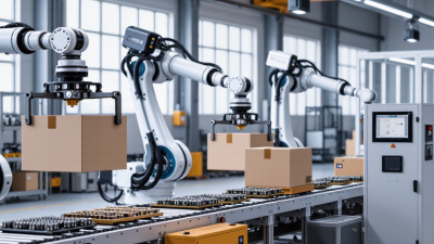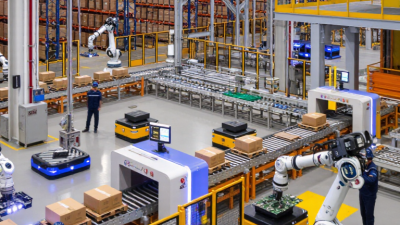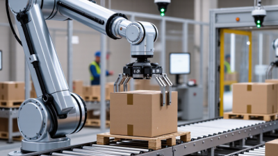
Robotic handling systems use programmed robots to move, position, load, and unload materials in manufacturing and logistics. A typical setup includes a robotic arm, a gripper or other end effector, sensors, a controller, and fixtures that hold parts in place. These components work together to transfer items between stations, such as a conveyor and a machine tool. The robot may handle a small metal component, a carton, or a heavier assembly, depending on its design and tooling.
How does the process work? A controller follows a programmed sequence, while sensors help locate parts or confirm that a grip is secure. The robot approaches, picks up an item, moves along a planned path, and places it at the next position. For example, a vision sensor might identify a part arriving at an angle, allowing the system to adjust its pickup point. Guards, interlocks, and risk assessments also matter; speed alone does not make a cell effective.
These systems can support more consistent handling and reduce repetitive manual tasks, but results depend on the application. Part variation, slippery surfaces, awkward shapes, and changing production volumes can complicate setup. Small details matter. A gripper that works well with one part may damage another or lose its hold. Even a neat cycle-time estimate can overlook maintenance, changeovers, or occasional misfeeds. Understanding the equipment and its limits makes it easier to judge where robotic handling systems fit—and where a simpler approach may work better.
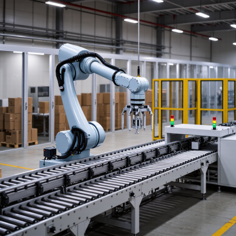
Robotic handling systems use programmable machines to move, position, load, or unload materials during production. Their scope includes the robot, end-of-arm tooling, sensors, control software, and the surrounding work cell. A gripper might lift a metal casting from a fixture, rotate it, and place it on a conveyor. That is the core.
In automated production, the system follows a defined sequence. Sensors locate a part or confirm that a station is ready. The controller sends the robot a motion path, while the tool grips or releases the item at set points. Safety devices and interlocks help coordinate movement with nearby equipment. Small details matter. A slightly shifted part can cause a missed pickup or a jam.
The term “handling” covers more than simple pick-and-place tasks. It can include machine tending, palletizing, sorting, and transferring parts between workstations. System design depends on payload, reach, cycle time, part shape, and how reliably parts arrive. A vision sensor may help with variable placement, but it does not fix every upstream problem. In practice, fixtures, lighting, and maintenance can matter as much as the robot. Automation is not always hands-off; operators may still need to replenish materials, clear faults, or adjust a process when real production differs from the planned sequence.
What Are Robotic Handling Systems and How Do They Work?
Core Components: Robot, Gripper, Sensors, and Cell Controller
A robotic handling system moves parts between work areas with repeatable motion. Its robot provides reach and movement, following programmed paths to pick, position, or transfer items. The gripper makes contact with each part. It may use fingers, suction, or another suitable mechanism, depending on the part’s shape, weight, and surface. A poorly matched gripper can mark delicate surfaces or drop an uneven load.
Sensors help the system respond to real conditions. A camera can locate a part, while presence or force sensors can confirm pickup and placement. The cell controller coordinates these inputs with the robot and nearby equipment. In a typical cycle, it checks that the work area is ready, directs the robot to collect a part, and verifies that the part reaches its destination. If a signal is missing, the system can pause instead of continuing blindly. Small details matter. Sensor placement and lighting can affect reliability.
Tips: Test with actual parts, including awkward orientations and small variations. Keep the pickup area consistent where possible. Review failed cycles before changing settings; the cause may be a loose fixture, not the robot. No setup is perfect, and even a well-tuned system needs periodic checks.
Illustrative time spent in each phase of a robotic pick-and-place cycle
A robot moves the part, a gripper secures and releases it, sensors help detect parts and confirm conditions, and a cell controller coordinates the equipment. The example cycle totals 2.5 seconds; actual times vary with the robot, payload, travel distance, and safety requirements.
Operating Sequence: Detect, Grip, Transfer, Place, and Verify
A robotic handling system moves parts between workstations through a controlled sequence. Detection starts with a camera, scanner, or presence sensor identifying an item’s position and orientation. The controller compares that information with the task settings. A gripper then closes around the part, using fingers, suction, or another suitable contact method. Small details matter. A reflective surface or loose part can affect detection, so real production lines often need careful testing under changing conditions.
During transfer, the robot follows a programmed path while speed limits and safety sensors help manage nearby activity. At the destination, it places the item against a fixture or within a defined tolerance. Then comes verification. A sensor or vision system checks whether the part arrived and, where needed, whether its position is acceptable.
The International Federation of Robotics’ World Robotics 2024 report recorded 541,302 industrial robot installations worldwide in 2023. This figure covers industrial robots broadly, not handling systems alone, but it shows the scale of automation. More robots do not guarantee better handling. Grip choice, calibration, and awkward part variations still deserve review.
A robotic handling system may lift a metal casting, rotate it, and place it into a fixture. Its safety depends on more than the robot arm. ISO 10218 provides safety requirements for industrial robots and integrated robot systems. The application still needs a task-specific risk assessment. Real hazards often appear where equipment meets: at grippers, conveyors, transfer points, and access doors.
Risk controls should match the actual workflow. Fences and interlocked gates can restrict entry; scanners or light curtains may protect open loading areas. Safe stopping functions and clearly reachable emergency stops matter, too. A collaborative mode is not a safety guarantee. The tool, payload, speed, and possible contact all affect risk. Small details count. A sharp workpiece edge can change the assessment.
Integration requires checks before operation and after meaningful changes. Verify that guards stop the system as intended, and test restart behavior with people outside hazardous areas. Document who may enter, how faults are handled, and how maintenance energy is controlled. A checklist can look complete while a real shift reveals awkward reach or blocked visibility. That gap deserves attention. Safety is not a one-time sign-off; it needs review as tasks, tools, and layouts evolve.
A robotic handling system uses a robot, end-effector, controls, and related equipment to move or manipulate parts. Safe integration requires assessing the complete application, including the robot, tooling, workpiece, people, and surrounding machinery.
| System Area | Typical Hazard | Example Risk Control | Integration Check or Evidence |
|---|---|---|---|
| Robot motion and reach | Impact, crushing, or trapping within the robot’s working area. | Define the operating space and restrict access with suitable safeguarding, such as fixed guards, interlocked access gates, or other measures selected through risk assessment. | Confirm the safeguarded space accounts for the robot, tool, workpiece, foreseeable motion, and stopping distance. Check access points and hazardous gaps. |
| End-effector and workpiece | Parts may be dropped, ejected, pinched, or have sharp or hot surfaces. | Assess gripping reliability and failure modes; secure tools and parts; use suitable retention, guarding, or exclusion measures where needed. | Test representative loads and operating conditions, including loss of power or grip where relevant. Document safe handling limits and inspection requirements. |
| Access doors and interlocks | A person may enter a hazardous area while the robot or associated equipment is operating. | Use appropriately designed interlocking safeguards. Where required by the risk assessment, prevent access until hazardous motion has stopped or apply guard locking. | Verify that opening a safeguard initiates the intended safety response and that bypassing or defeating the safeguard is controlled. |
| Presence detection | A person may approach or enter an area with moving equipment. | Where suitable, use presence-sensing safeguards, such as light curtains or safety scanners, with positioning and protective distances based on the application and stopping performance. | Validate detection coverage, blind spots, response behavior, and stopping distance under the installed operating conditions. |
| Collaborative operation | Contact between a person and the robot, tool, or workpiece may cause injury. | If collaborative operation is intended, select and validate applicable methods such as safety-rated monitored stop, hand guiding, speed and separation monitoring, or power and force limiting. | Assess the complete application, including tool and workpiece hazards. Verify the selected method and limits under foreseeable contact and operating conditions. |
| Safety-related controls | A control fault may prevent a protective function from working as intended. | Specify safety functions and required performance from the risk assessment; implement them using suitable safety-related control components and architecture. | Review design documentation and validate each safety function, including its response to relevant faults. Required performance is application-dependent. |
| Emergency stop | An unexpected event may require an accessible means to stop hazardous operation. | Provide accessible emergency-stop devices where required. Treat emergency stop as a complementary measure, not a replacement for guarding or other risk reduction. | Check device locations, reset behavior, and the stopping response. Ensure resetting an emergency stop does not itself restart the robot. |
| Restart and mode selection | Unexpected startup or an incorrect operating mode may expose people to motion. | Design start and reset controls to prevent unintended restart. Control access to operating modes and use enabling devices where required for setup or manual intervention. | Test restart after safeguard closure, power restoration, fault recovery, and mode changes. Confirm people can leave hazardous areas before automatic operation resumes. |
| Electrical and stored energy | Electric shock or unexpected movement from electrical, pneumatic, hydraulic, or other stored energy. | Provide suitable electrical protection and means to isolate and dissipate hazardous energy for maintenance and intervention. | Verify isolation points, labeling, and safe maintenance procedures. Check that stored energy cannot cause hazardous movement after isolation. |
| Commissioning and maintenance | People may be exposed during teaching, fault finding, cleaning, or repair. | Establish controlled setup and maintenance procedures, including appropriate mode selection, access control, isolation, and personnel training. | Keep risk assessments, validation records, operating instructions, and maintenance checks current when the cell or its use changes. |
This table is an overview, not a complete compliance checklist. Apply the relevant edition of ISO 10218 and applicable local requirements; use a documented risk assessment for the full integrated application. Other standards may also apply, including ISO 12100 for risk assessment and risk reduction, IEC 60204-1 for electrical equipment of machines, and ISO/TS 15066 where relevant to collaborative robot applications.
In 2023, factories worldwide installed 541,302 industrial robots, according to the International Federation of Robotics (IFR). That was the second-highest annual total on record, although installations fell about 2% from 2022. The scale is striking. Still, this figure counts industrial robot installations, not robotic handling systems alone. It signals strong automation activity, but needs that distinction.
A robotic handling system uses a robot to move materials or parts through a process. It might lift a metal blank from a feeder, place it into a machine, then transfer the finished part to a tray. Sensors, grippers, safety equipment, and control software help coordinate those movements. In a busy cell, small changes in part position can interrupt the rhythm. The robot may be fast; the whole system is only as reliable as its setup.
The IFR total provides useful industry context: automation is being adopted at substantial scale. But installation numbers do not reveal how efficiently each system performs, or whether workers received enough training. A handling cell also needs suitable floor space, dependable part supply, and regular maintenance. These practical details are easy to underestimate. Sometimes, a simpler layout works better than a more ambitious one.