


What Are the Top 10 Extruder Machine Parts?
Extruder Machine Parts work together to move, melt, shape, and discharge material at a controlled rate. A typical line may include a feed throat, screw, barrel, gearbox, drive motor, heaters, temperature sensors, screen pack, die, and cooling equipment. Each component has a specific role, but performance depends on how the parts interact. A worn screw, for example, can reduce output even when the motor appears to run normally.
This guide examines ten key parts and explains what they do, what operators can inspect, and how problems may affect production. Details vary between single-screw and twin-screw machines, as well as between polymers and other materials. So a parts list is a starting point, not a universal specification. Small details matter. A blocked screen pack may raise pressure, while uneven barrel heating can affect melt consistency. These clues are useful, but they do not replace the machine manual or a qualified technician’s assessment. It is also easy to focus on obvious wear and overlook alignment or temperature readings. That can happen. Understanding each part makes routine checks more informed and helps readers ask better questions before selecting replacements or troubleshooting an extrusion line.
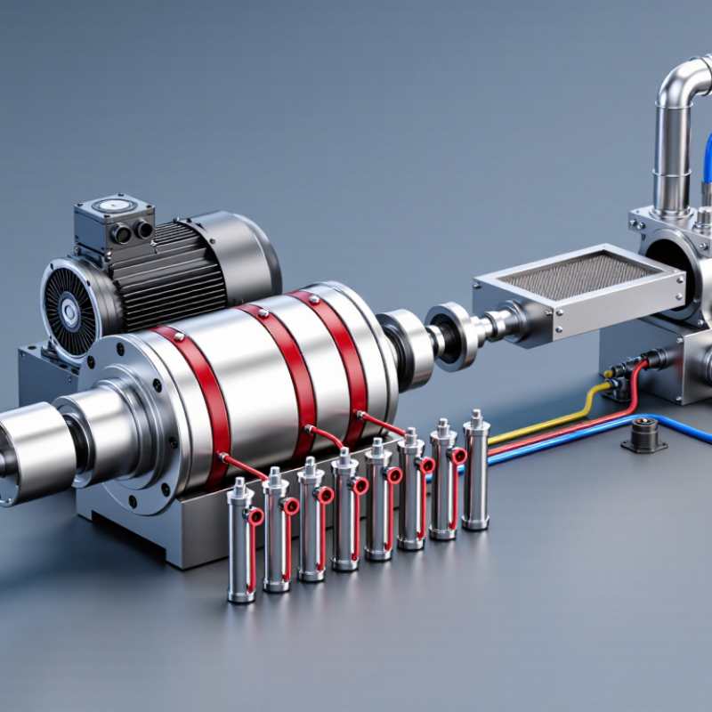
Material Entry: Hopper and Feed Throat
Material entry begins at the hopper, where pellets or regrind are held before entering the barrel. Its shape and capacity affect how steadily material reaches the screw. A steep, smooth-sided hopper helps granules slide down, while ledges or damp residue can encourage bridging. Small detail, big effect. Operators should check for clumps, dust, and inconsistent pellet size before a run. A level sensor can help prevent an empty feed, but it cannot confirm that material is flowing freely.
The feed throat connects the hopper to the heated barrel and guides material toward the screw. It is often cooled to keep polymer from softening too early and sticking near the opening. Cooling needs to be verified, not assumed: a blocked water line or poor contact may let heat creep upward. Watch for uneven output, surging, or unusual noise, then inspect the throat and feed zone using the machine maker's procedures. Keep guards in place and avoid reaching into moving equipment. A dry, clean interface matters. Yet cleaning alone will not fix a poorly matched feed design; that point is easy to miss. Material behavior varies with moisture, particle shape, and temperature, so records from actual runs are more useful than guesswork.
What Are the Top 10 Extruder Machine Parts? - Material Entry: Hopper and Feed Throat
| Part or Component | Main Function | Typical Design and Operating Notes | Routine Inspection |
|---|---|---|---|
| Material Hopper | Stores pellets, flakes, or other feedstock above the extruder and directs it toward the feed opening. | Often uses sloped walls to encourage material flow. Hopper size and outlet geometry should suit the feed material and required production rate. | Check for bridging, residue, moisture, contamination, and secure mounting. |
| Hopper Outlet | Controls the transition from the hopper into the feed throat. | The opening should align with the throat and provide a clear path for the material. Outlet design is selected to reduce hang-ups and uneven feeding. | Look for blockages, worn edges, or material buildup around the opening. |
| Feed Throat | Guides material from the hopper into the extruder barrel and screw channel. | It is positioned at the feed section of the barrel. Its geometry and surface condition can affect material flow into the screw. | Check for obstructions, wear, leaks, and signs of overheating. |
| Feed-Throat Cooling Jacket | Removes heat from the feed-throat area to help prevent premature softening of the polymer. | May circulate water or another specified coolant through passages around the throat. Cooling requirements depend on the material and process conditions. | Inspect coolant flow, connections, and passages for leaks, scale, or blockage. |
| Feed-Throat Liner | Provides a replaceable contact surface inside the feed opening on designs that use a liner. | Material and surface finish are chosen for wear resistance and compatibility with the feedstock and machine design. | Check for scoring, distortion, loose fit, and excessive wear. |
| Hopper Magnet | Captures ferrous metal fragments before they can enter the screw and barrel. | May be installed in the hopper outlet or a material passage. It is a contamination-control device, not a substitute for proper material handling. | Remove collected metal safely and clean the magnet at the interval required by the process. |
| Hopper Screen or Grate | Helps keep oversized foreign objects out of the feed opening and can provide a basic safety barrier. | Opening size and construction should allow the intended material to pass without restricting normal feeding. | Check for damage, blockage, or material accumulation; never bypass required guarding. |
| Material-Level Sensor | Detects material level in the hopper and can signal a low-level condition or control replenishment. | Sensor type and placement depend on the material, hopper geometry, and whether the system detects point level or continuous level. | Verify the sensor is clean, correctly positioned, and responding to changes in material level. |
| Hopper Dryer | Conditions moisture-sensitive pellets with heated, dehumidified air before they enter the extruder. | Drying temperature and time must follow the material supplier’s guidance; excessive heat or inadequate drying can affect processing and product quality. | Check air temperature, airflow, desiccant condition where applicable, and dryer-to-hopper connections. |
| Vacuum Loader and Pickup Line | Transfers material from a storage container or central supply to the hopper or dryer. | Typically includes a receiver, filter, conveying line, and controls. Line layout and conveying settings should suit the material and avoid excessive degradation or separation. | Inspect filters, seals, hoses, and pickup points; clear material buildup and confirm reliable loading cycles. |